

Lista produktów
![]() Professional Telematic Device
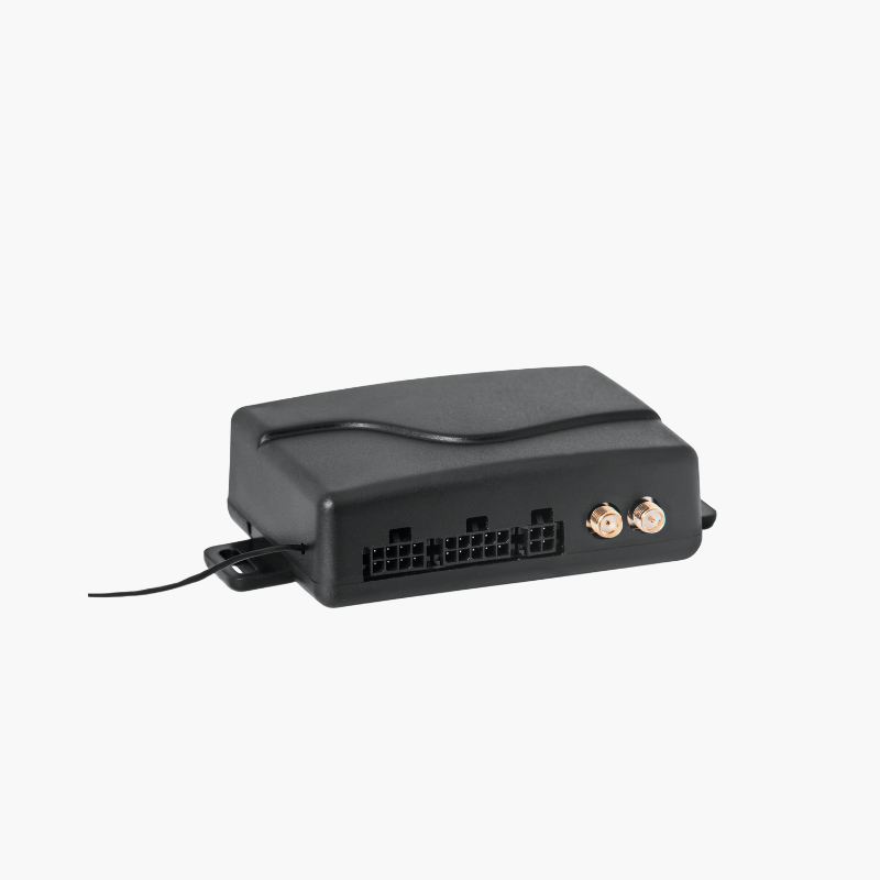
Professional Telematic Device
Small Version


Pliki do pobrania
Karta Professional Telematic Car Alarm
Zdjęcia


PTCA
Professional Telematic Car Alarm
Homologation number: E20 97R01/08 *004030*00

Based on over three decades of experience in the automotive industry, we have created a hybrid of a car alarm and a telematics device, dedicated to applications in vehicles with 12V and 24V installations. The PTCA control panel is a professional class alarm device with E97 homologation entitling you to obtain a discount on vehicle insurance.
Professional Telematic Car Alarm (PTCA) is a homologated device intended for installation in cars and trucks. The terminal performs two most important functions:
- Vehicle anti-theft protection, e.g.: *
- alarm arming/disarming control,
- control of opening / closing doors, trunk lid and bonnet,
- control of the angle of the vehicle inclination (towering),
- control of signals from additional alarm sensors, e.g. motion sensor, impact sensor,
- anti-attack function,
- dual-circuit immobilizer function.
In the event of violation, the alarm siren is activated and the appropriate information is sent via the GSM network.
* Depending on the type of additional safety devices installed.
- Supporting logistic processes and security monitoring options (integration with the alarm monitoring center) through access to a lot of information obtained from the vehicle, e.g.:*
- geolocation of journeys and stops,
- vehicle speed,
- information about events, e.g. ignition on/off, door opening,
- counter status,
- precise information on all alarm events (protective monitoring).
* Tools supporting logistic processes and the type of security services provided depend on the functionality of the service provider's system.
Information obtained by the PTCA terminal is transferred via the GSM network directly to the end user (via SMS messages) or through the use of a full open communication protocol to the indicated address of the server receiving and processing the obtained data (internet transmission of the GSM network).
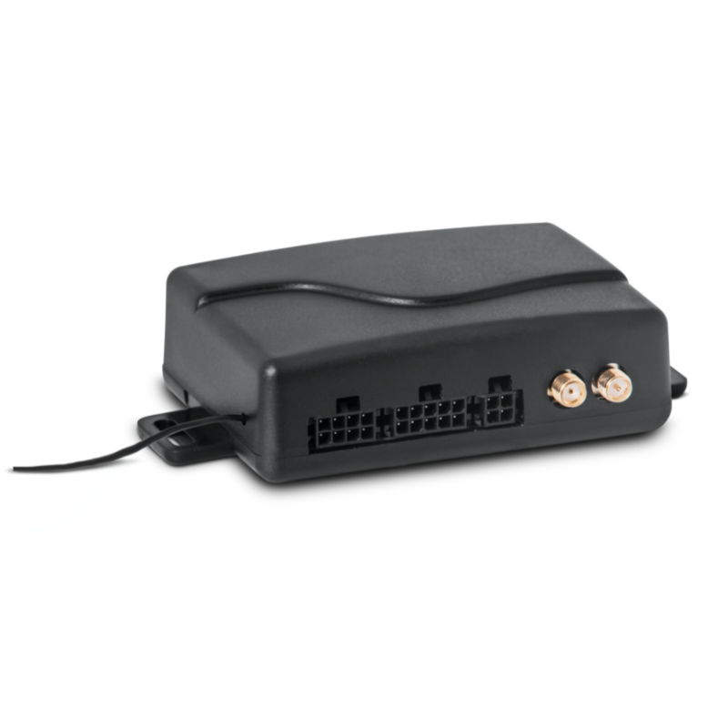
The PTCA kit includes:
- Control panel designed from scratch by our engineers.
- Maintenance-free rolling code keyfob (with built-in motion sensor).
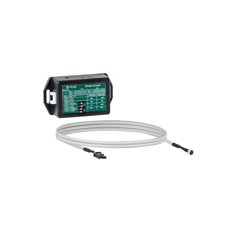
- Door opening detection module connected to the lighting lamp, communicating radio (wireless) with the alarm control panel.
- Module containing two disconnection relays and a traffic light relay.
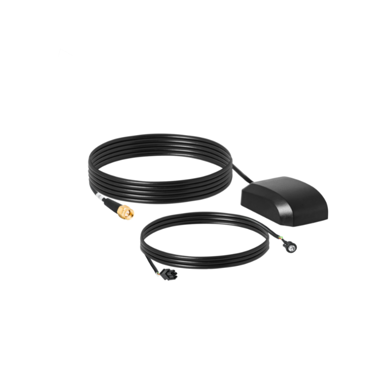
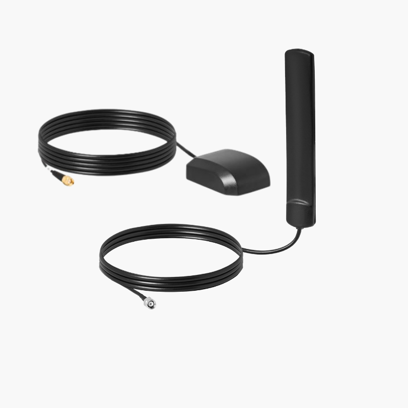
- Cable harnesses, GPS antenna, GSM-GPRS antenna.
- Cabin listening microphone.
- External LED light notifications of alarm status (e.g. armed, disarmed, service status).
- The sound signal after detecting an alarm incident lasts 30 seconds and is turned off.
- Automatic arming of the alarm when the keyfob lacks connection with the control panel.
- Automatic disarming of the alarm when establishing the connection between keyfob and the control panel.
- Programmable auto-arm time function.
- Panic button function. Holding the hidden button in the vehicle cabin, sends the alarm according to the programmed rules (the so-called silent alarm - does not activate the siren). The function does not change the logical state of arming/disarming the alarm.
- All alarm functions are programmed remotely via SMS.
- Possibility of remote update of the alarm software.
- System power supply from +7V to +36V.
- Average current consumption tested with the following assumptions:
- no power supply to external components,
- inactive alarm siren,
- charged backup battery (or no battery),
- alarm in standby mode,
- current drawn from the car battery:
12 mA +/- 5% for Usup = 12,6V,
8 mA +/- 5% for Usup = 25,2V.
- Operating temperature from -30⁰C to +70⁰C.
- Alarm siren control output max. 0.7A.
- 8 inputs permanently assigned to specific functions.
- 3 outputs dedicated to relays control.
- 1 output for powering additional sensors, max 0.3A.
- Internal sensor (3D) for tilt and towing (from 2° to 10°).
- Operating frequency of the keyfob and radio door module: 868.35MHz.
- Control panel and door module housing: ABS (for installation inside the car cabin).
- ABS IP65 keyfob housing.
- Dimensions:
- Central unit:
- hight: 30 mm,
- width: 114 mm,
- depth: 64 mm.
- Door module:
- hight: 21 mm,
- width: 65 mm,
- depth: 35 mm.
- Keyfob:
- hight: 18 mm,
- width: 60 mm,
- depth: 40 mm.
- Central unit:
- Connectivity: GSM/GPRS modem.
- Weight:
- central 80g.
- door module 25g.
- remote control with battery 36g.
- Internal GPS antenna:
- frequency 1575.42 MHz,
- impedance 50 Ohms,
- current 10 mA DC,
- polaryzacja RHCP,
- V.S.W.R. 1,5dB,
- gain 28dB,
- working temperature from -40⁰C to +85⁰C,
- Internal GSM antenna:
- frequency: 824~960 MHz/1710~1990 MHz, 1920~2170 MHz,
- VSWR≤2,0:1,
- gain: 2dBi,
- impedance: 50 Ohms,
- Support for external 12/24V gel battery.
- Integrated charging system.
- Suggested capacity up to 7000mAh.
- Continuous monitoring of battery wear.
- Low battery alert.
- Maintenance-free keyfob.
- Automatic arming / disarming of the alarm by communicating with the alarm control panel.
- Information about low battery status (SMS notification).
- Communication with the terminal using a randomly changing 32-bit code.
- Ability to program up to four keyfobs for one alarm.
- Built-in 3D sensor – in case of no movement, the keyfob stops transmitting the code. The function protects against copying the remote control in the event of theft and significantly reduces battery consumption.
Tipping and towing the vehicle. Changing the vehicle position account by 2 degrees from the stored position when the alarm was last armed.
- INPUTS
- C_01: Additional input dedicated to the motion sensor ……….....................................................[NO+; NO-] High alarm function.
- C_02: Additional input dedicated to the impact sensor ...................................... ....…...........[NO+; NO-] High alarm function.
- C_03: Additional input dedicated to connect the door drzwi………….....................................[NO+; NO-] Alarm function from input status change.
- C_04: Additional input dedicated to connect the trunk lid……...............................................[NO+; NO-] Alarm function from input status change.
- C_05: Additional input dedicated to connect the engine hood …....................................…[NO+; NO-] Alarm function from input status change.
- C_06: Vehicle ignition switch on signal………..........................................................................………......[NO+; NO-] Alarm function from input status change.
- C_07: Alarm auto-arm blocking signal......................................................................................………….[NO+; NO-] No alarm function from input status change.
- C_08: Anti-attack signal……...........………..............................…………………....………………………………………….[NO+; NO-] Silent alarm function from high input state.
- OUTPUTS
- W_01: Programmable output, controlled by ground, to control the immobilizer relay.
Programmable as:- switched on during the alarm standby after the ignition signal appears,
- switched on permanently during the alarm standby.
- W_02: Programmable output, controlled by ground, for switching on the immobilizer relay.
Programmable as:- switched on during the alarm standby after the ignition signal appears,
- switched on permanently during the alarm standby.
- W_03: Programmable, ground controlled output for switching on the light relay.
Programmable as:- activated during alarming with a frequency of once per second,
- activated for the alarm time,
- activated for 1 second at the beginning and at the end of alarming.
- W_04: +12V output (load capacity 70mA) for supplying alarm components when working in a 24V system.
- W_05: Ground controlled output (load capacity 300mA) switched on during the alarm standby to power the alarm components.
- W_06: Siren output controlled by the plus of the alarm power supply (load capacity 0.7A), activated for the time of alarming.
- W_01: Programmable output, controlled by ground, to control the immobilizer relay.
Information passed as a high state of the emulated physical input.
- P_01: Alarm armed or alarm at rest.
- P_02: Alarm in service state.
- P_03: Alarm siren activated.
- P_04: Tow sensor activity.
- P_05: Motion sensor activity.
- P_06: No main alarm power supply.
- P_07: Low battery in the alarm key fob.
- P_08: Unauthorized vehicle driving (without the keyfob).
The wireless expansion module allows to obtain information about the opening of the vehicle door using the signal of the interior lighting of the cabin. Module compatible with cabin lighting with dimming function.
The terminal allows to program up to four mobile phone numbers, to which information about alarm conditions will be sent as SMS messages, along with the current location of the terminal provided as a link to the Google map. After sending the SMS, the Voice Call function will start - the terminal will call the defined telephone number.
All information obtained by the PTCA terminal can be transferred using the GSM network (data transmission based on public or private encryption). This is done using a full, open communication protocol. A complete set of information obtained by the terminal at a given moment is sent to the indicated address of the server that receives and processes data. Thanks to this, the PTCA terminal enables integration with any IT system, ensuring the receipt of all data described in the protocol. Recording can be done in several ways.
- Basic parameterization.
The basic configuration of sending records has been divided into three groups. Different parameters are programmable for each.- Ignition switched on:
- elapsed time since the last information sent (second interval),
- distance traveled (meter interval),
- twist greater than XX degrees (turn angle interval).
- Ignition switched off:
- elapsed time since the last information sent (second interval).
- Ignition switched on:
- Advanced, asynchronous parameterization.
Incident record. Changes in the status of inputs or outputs result each time in a record being sent with information about incidents, regardless of the status of the ignition switch and main power supply.
Changing individual parameters is possible by:
- Local configuration using the service program by connecting a cable to the terminal.
- Remote configuration via dedicated SMS commands or an application installed on Android phones.